Sonify
Messenger over sound waves.
Transferring Bits with Sound
Video Explanation
Direct Link Here: https://www.youtube.com/watch?v=eeCN8XOj45g
The Basic Idea
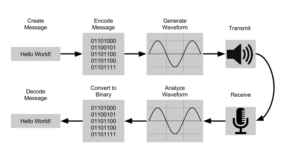
Our project goal is to transmit messages from one device to another using sound waves in the audible frequency range. Below, you can see a diagram of our system, which includes user input, conversion to binary, waveform encoding, and waveform decoding back into the original message (hopefully).
A Demo
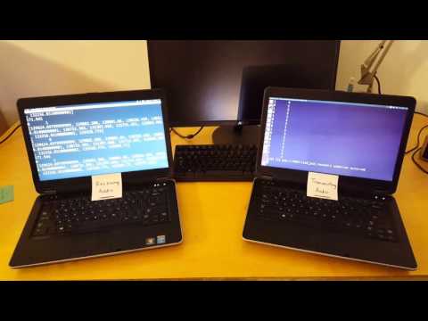
Here is a demonstration of our software allowing a message to be transmitted from one device to another. The device on the right is encoding the message into the audible frequency and playing it through speakers, while the device on the left records the audio and analyzes it in the frequency domain to decode the message.
Encoding Data
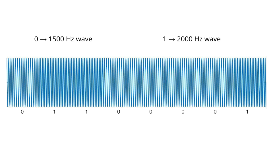
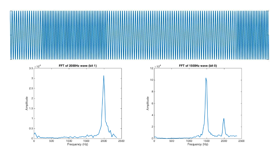
In order to store data in a sound wave, we decided to create a simple two-tone wave where a first tone, 1500 Hz, represents a binary 0 and a second tone, 2000 Hz, represents a binary 1. This generated two-tone wave is then transmitted over the first device’s speakers.
Decoding Data
The decoding process begins with the second device streaming in audio and running a live fast fourier transform on the wave. This FFT allows us to analyze the wave in the frequency domain and see what frequency tones are most prevalent (typically either 1500 Hz or 2000 Hz).
We use the information that we gather from the FFT to determine where there are sharp changes in frequency either from 1500 Hz to 2000 Hz or from 2000 Hz to 1500 Hz. When one of these two frquency change events occurs, we mark the current time and append it to an array.
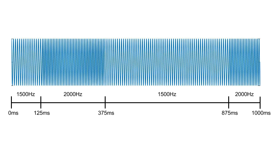
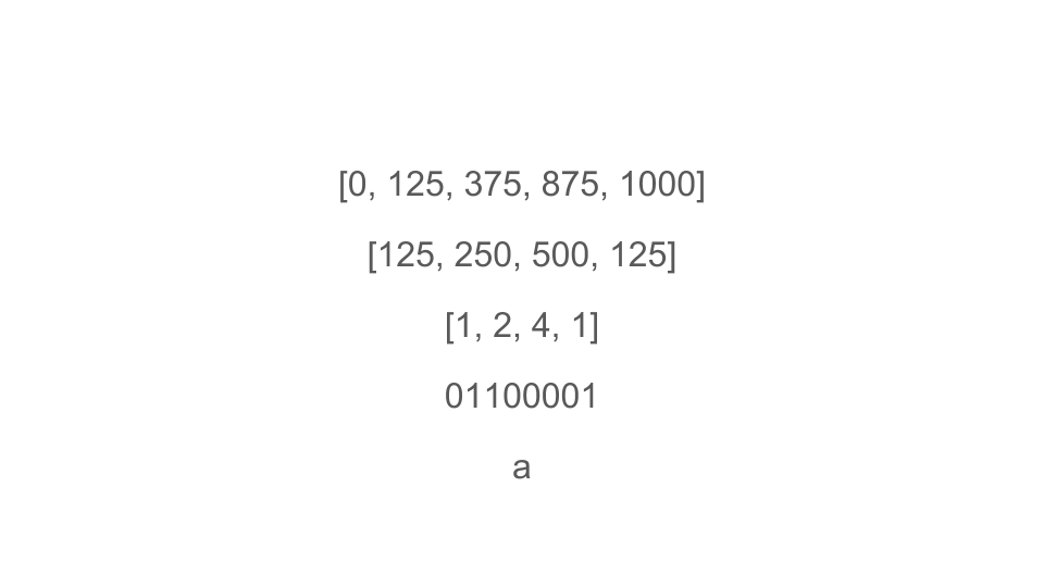
When can then use this array of saved times to calculate how long each series of 0s and 1s occurred for and decode the original binary sequence, which allows us to get back the original tramsitted message.
Accuracy Tradeoff
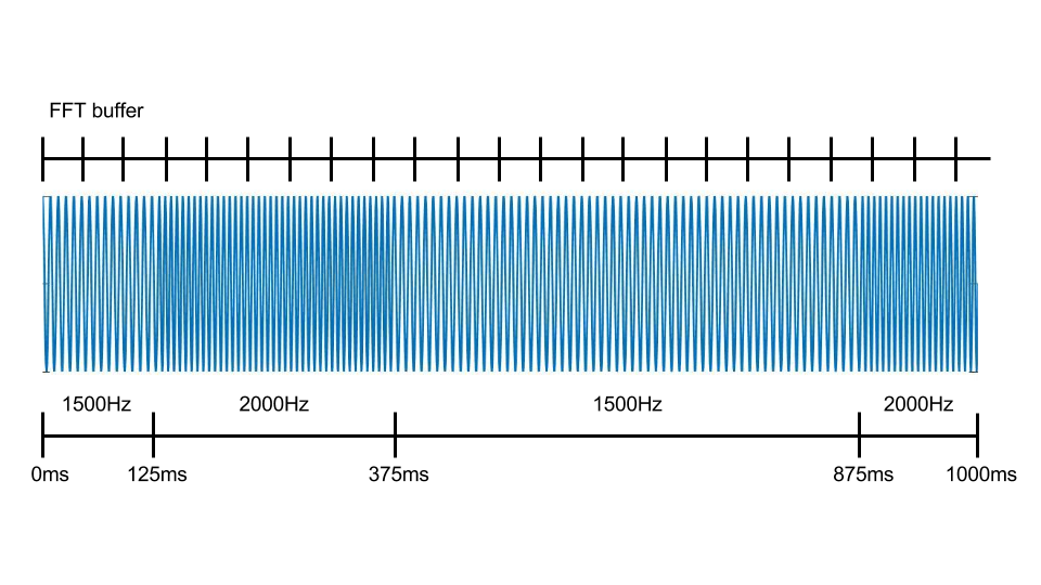
The image below is a representation of how we took the FFT across our audio signal. We chose the size of our FFT buffer to change the accuracy of frequency detection (larger FFT buffer decreases bin size) and the speed of FFT computation (smaller FFT buffer is faster). We had to optimize the buffer size to perform an FFT that computes accurately in the frequency domain and quickly in time.
Future Work
A more efficient implementation of this communication could use matched filtering or phase shift keying.
Matched Filtering
When receiving a signal with a known set of signal states, you can ignore noise that does not exist within one of these known states. The set of all known states of a signal is called the template. If an unknown signal is convolved with its conjugated time-reversed template, then the unknown signal will converge to the set of known signal states, effectively eliminating accumulated noise. The process of eliminating noise in this way is known as matched filtering. The image below depicts this process.
 Image from Wikipedia
If we had implemented matched filtering in our project, then we would effectively be running a DFT with only two bins focused around 1500 Hz and 2000 Hz. This would significantly increase our frequency accuracy and computation speed, making this communication method more effective and accurate.
Phase Shift Keying (PSK)
Phase shift keying works similarly to what we implemented. However, only one frequency is used and the phase (rather than the frequency) of the wave specifies the bit. PSK is more efficient because it wastes less frequency space, as only one frequency is used. However, we would need to filter for the specific frequency before being able to determine phase. The image below depicts simple 180° phase shift keying.
Image from electronicdesign.com
Possibly some combination of matched filtering and phase shift keying would allow for a very robust and efficient system.